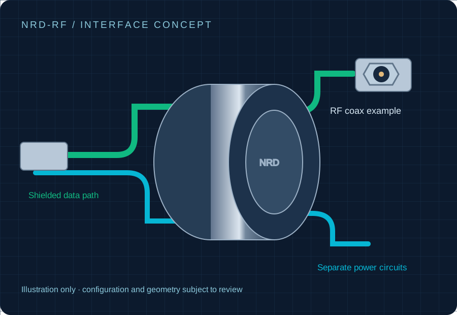
DATA RATE × POWER × CONNECTOR
Define the assembly before the part number.
Requested design envelopes, subject to configuration review. Dimensions, current and maximum RPM are not interchangeable across assemblies.
ENGINEERING REVIEW
Radar / Antenna / Optical data: what determines fit?
- 50 Ω or 75 Ω selected per coaxial path
- Frequency-dependent insertion loss and VSWR
- Single-mode / multimode FORJ and link budget
A 10 Gb/s optical link is not 10GBASE-T copper Ethernet. VSWR, insertion loss and 40 GHz capability require a model-specific report over the requested band. Connector and adapter frequency ratings must cover the complete band; 40 GHz requires a suitable precision interface.
Bring these inputs to the RFQ
- Frequency band, RF power and channel isolation
- Maximum insertion loss and rotational variation
- Optical wavelength, fiber count, mode and connector
For antenna, radar test and high-bandwidth rotating platform engineers.
POWER + DATA / EMC REVIEW
Specify how the shield crosses the rotation.
NRD configuration review
- Define a separated power / data path and shield termination.
- Agree protocol-specific impedance and channel test criteria.
- Test while rotating with servo power energized.
Unspecified rotary interface risks
- Continuity checks can miss high-frequency discontinuities.
- Uncontrolled pair routing can increase coupling.
- Static cable tests can miss speed- or load-related errors.
Engineering comparison of test scope; no unmeasured numeric crosstalk or packet-loss result is implied.
CONFIGURE / NRD-RF
Define the rotary interface.
Send the operating conditions that determine a useful quote. Connector, cable and test scope selections travel with your request.
RELATED DATA INTERFACES
Review adjacent signal families.