
GigE Vision & LiDAR
Camera payload, frame timing and uninterrupted mechanical rotation.
SIGNAL-FIRST ROTARY CONNECTIONS
Gigabit Ethernet, EtherCAT, USB 3.0 and video interfaces for machines that never stop rotating.
Compact capsule assemblies. Shielded RJ45 and M12 connectors. Power and data specified together.
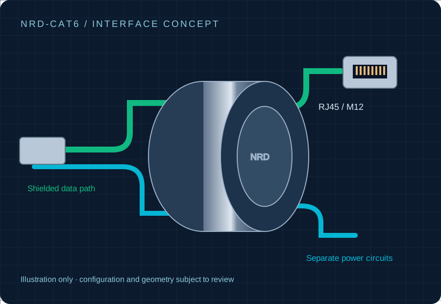
FIVE DATA INTERFACE FAMILIES
Start with the data architecture. Add motor power, lighting circuits and the connector arrangement your integration needs.
Ethernet / GigE Vision
100Base-TX / 1000Base-T
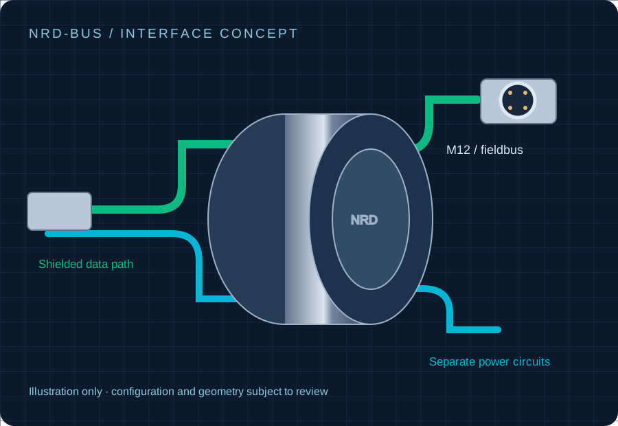
PLC / Real-time fieldbus
Protocol-specific validation
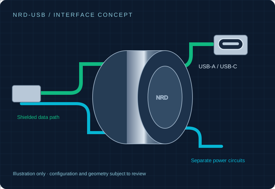
USB3 Vision / Rotary cameras
USB 2.0 480 Mb/s / USB 3.0 5 Gb/s
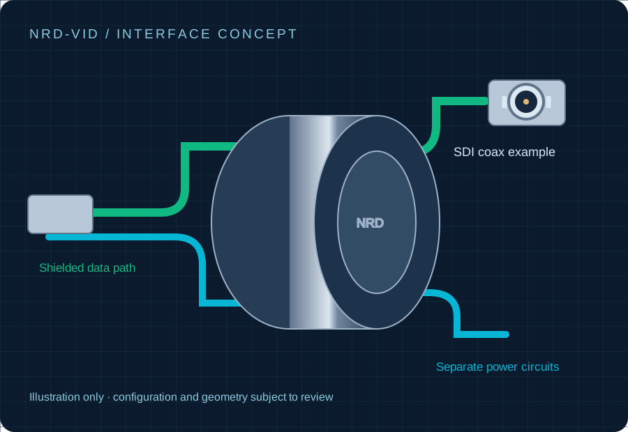
Broadcast / Optical gimbals
HDMI 2.0 / DisplayPort / 3G & 12G-SDI review
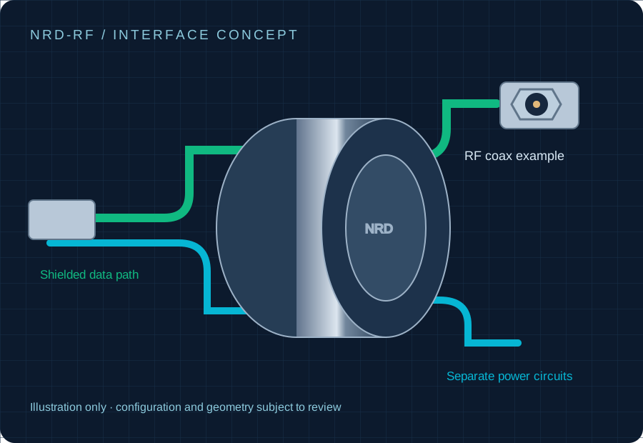
Radar / Antenna / Optical data
DC–18 GHz / 40 GHz review; optical link review
ROTATION CHANGES THE CHANNEL
CRC errors, dropped frames and PLC bus faults can follow impedance discontinuities, shielding gaps or power-circuit noise. A rotary Ethernet path needs a channel-level test plan.
Read the packet loss & EMC guide →Review Ethernet differential impedance, pair balance and the complete cable budget.
Specify motor current, shield termination and the actual servo drive environment.
Record speed, load, test duration and link counters with the real source and receiver.
Camera payload, frame timing and uninterrupted mechanical rotation.
Fieldbus cycle time, topology and power/data EMC integration.
Exact video format, RF bandwidth or optical link budget.
START WITH THE SIGNAL PATH
Share the protocol, power circuits, connectors and operating speed.